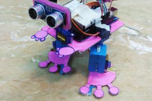
Raspberry Pi Pico W taught this car to avoid objects

Creating an obstacle-avoiding robot car might sound like one of the trickier Raspberry Pi builds you can attempt, what with all the motors, drivers, and sensors you need. But Karam Haddad makes it look easy-peasy in his seven-minute build video.

How does it work?

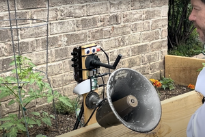
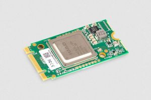
The brain of the robot car is a Raspberry Pi Pico W, chosen because it’s small enough to hide neatly inside the chassis but packs the necessary processing power to handle the control logic required for navigation. An ultrasonic sensor mounted on a servo motor enables the car to gauge its environment by taking distance readings in all directions. “That wall is seven metres away, so I should stop driving towards it in around 6.9 metres’ time,” is the kind of thing the car would say to itself. The robot is trained always to favour forward movement when the path is clear and only to evaluate alternative paths when an object is detected.

The image displays a graphical presentation of the main parts used in a DIY robotic vehicle. It is divided into sections, each highlighting a different component with an image and a label: MEGO Power Supply: Shown at the top left, this is a portable power supply unit with various input and output options. L298N Motor Driver: Located next to the power supply, this is a red circuit board used for controlling the motors of the robot. 2 DC Motors: Illustrated on the top right, these are yellow-cased motors that power the movement of the robot. Servo Motor: Below the power supply, there’s a blue servo motor, typically used for precise control of angular or linear position. Ultrasonic Sensor: Next to the servo motor, this sensor (blue with two circular elements) is used for distance measuring. Pico W: At the bottom right, this small green circuit board is a microcontroller unit with wireless capabilities. Tires: Accompanying the DC motors, shown at the very right, are wheels with yellow hubs and black tires, which facilitate the robot's mobility. The layout is clear and educational, providing a quick overview of the essential components involved in building a basic robotic vehicle.
All images screengrabbed from Karam’s build video

An adjustable DC power supply is powering the robot. A motor driver regulates the direction and speed of the DC motors attached to each wheel of the car.

The image shows a close-up of a DIY robotic vehicle on a carpeted floor. A hand is reaching towards the robot, possibly for adjustment or demonstration. The robot features a variety of components: Chassis: The base of the robot has large yellow wheels, providing stability and mobility. MEGO Power Supply: Mounted on the robot, this white box supplies power and displays a digital readout (not visible in this view). Ultrasonic Sensor: Mounted on a bracket at the front of the robot, this sensor has two cylindrical elements for distance measurement. Electronic Components: There are several boards and a mass of wires visible, indicating a complex setup likely involving a microcontroller and motor drivers. Servo Motor: Visible as part of the steering or operational mechanism. This setup seems to be part of a robotics project or hobbyist activity, demonstrating the integration of mechanical and electronic engineering components. The context suggests testing or development, typically seen in educational or DIY technology environments.

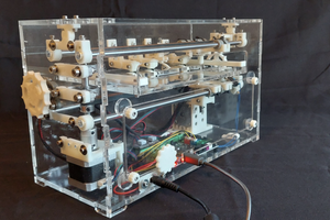
The physical chassis of the car, including bespoke mounts for the motors and sensors, was 3D printed and hot-glued together.

The image shows a close-up view of someone working on a DIY robotic vehicle at a desk. In their hand, they hold an ultrasonic sensor module, which consists of two round sensors on a blue circuit board. The workspace features several components: Robot Chassis: The base of the robot includes wheels and various mounted electronic parts. Ultrasonic Sensor: Currently being held, this sensor is used for distance measurement. Power Supply: To the left, a portable power supply labeled "MEGO" displays a voltage reading of 7.41 volts. Microcontroller Board: A green circuit board, possibly a Raspberry Pi or similar, with other connected electronic components and wires. Servo Motor: Visible as part of the robot's hardware, potentially used for steering or other movements. In the background, the desk is equipped with a mechanical keyboard and a modern computer mouse, suggesting this setting is a well-used personal or work area for technological projects.
Getting everything wired up

Uh-ohs and upgrades

Karam had to do some jiggery-pokery to address voltage drops during testing which left the motors without enough power, but after that the robot was ready for a road test around a makeshift obstacle course. The maker would like to explore the possibility of integrating smartphone connectivity, which would let you manually control the robot.

The image features a DIY robotic vehicle on a carpeted floor, facing a pair of worn cowboy boots. The robot has wheels, wires, and a couple of electronic modules, including one with a digital display showing "609". Above the scene, a strip of LED lights is mounted along the baseboard, illuminating the area with a soft glow. The setting appears to be a home environment, suggested by the domestic-looking carpet and wall base. The juxtaposition of the traditional cowboy boots with the modern, homemade robot creates an interesting contrast between rustic and technological elements.
Assessing the scene

Head to GitHub for all the code, and give Karam’s build video a like on YouTube.